Gear
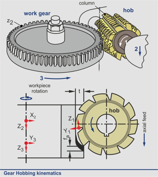
hobbing, as any cutting process based on the rolling principle,
is a signally multiparametric and complicated gear fabrication
method. Although a variety of simulating methods has been
proposed, each of them somehow reduces the actual three-dimensional
(3D) process to planar models, primarily for simplification
reasons. The paper describes an effective and factual simulation
of gear hobbing, based on virtual kinematics of solid models
representing the cutting tool and the work gear. The selected
approach, in contrast to former modeling efforts, is primitively
realistic, since the produced gear and chips geometry are normal
results of successive penetrations and material removal of
cutting teeth into a solid cutting piece. The algorithm has been
developed and embedded in a commercial CAD environment, by
exploiting its modeling and graphics capabilities.
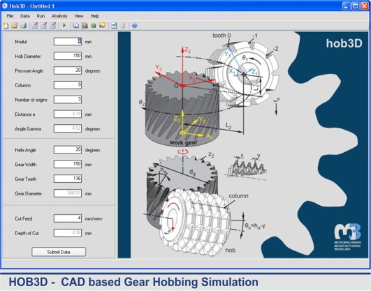
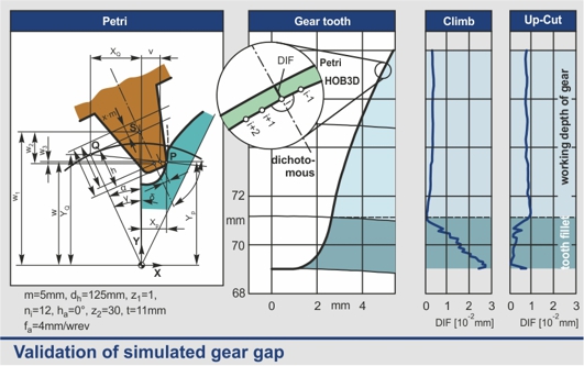
3D Simulation - Program HOB3D
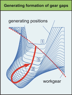
To
generate the produced chip and gear
volumes, the hobbing kinematics is
directly applied in one 3D gear gap.
The cutting surface of each
generating position (successive
cutting teeth) formulates a 3D
spatial surface, which bounds its
penetrating volume into the
workpiece. This surface is produced
combining the relative rotations and
displacements of the two engaged
parts (hob and work gear). Such 3D
surface “paths” are used to split
the subjected volume, creating
concurrently the chip and the
remaining work gear solid
geometries.
This
algorithm is supported by a
universal and modular code as well
as by a user friendly graphical
interface, for pre- and
postprocessing user interactions.
The resulting 3D data allow the
effective utilization for further
research such as prediction of the
cutting forces course, tool
stresses, and wear development as
well as the optimization of the gear
hobbing process.
Gear gap verification
Wear Deretmination
Gear
hobbing is an efficient method of gear manufacturing. Due to the
fact that during the cutting process every hob tooth always cuts
in the same generating position, while in the various generating
positions the formed chip has different geometry, the resulting
tool wear is not uniform on any particular hob tooth. In order
to overcome this problem, the hob is shifted tangentially after
a certain number of cuts. Mathematical models to calculate the
progress of hob wear in the individual generating positions,
considering the existing process parameters, were presented. In
order to calculate flank wear regarding the complicated chip
geometry, equivalent chip dimensions, such as the cutting length
l, the chip thickness hs and the characteristic chip form (chip
group) were introduced. Based on these calculations, a computer
algorithm for the determination of the hob flank wear, which
depends on the shifting conditions, was presented.
Simulating
the hobbing process with the aid of a computer program, it is
possible to determine the length, thickness and group of every
chip in the various cutting and generating positions. With the
aid of these parameters, the progress of the flank wear on a hob
tooth during cutting in the same generating position in all
successive cutting positions along the gear width can be
determined. This procedure is repeated for all generating
positions.
To optimize the shift displacement and amount, the course of the
flank wear versus the number of hobbed gears is calculated in
every individual generating position as well as the wear
distribution at the hob teeth. The calculated number of hobbed
gears and the occurring width of the flank wear, using various
shift conditions. The shift displacement is expressed as a
multiple of the hob axial pitch ε. Using such diagrams the shift
displacement and amount can be determined with respect to a
prescribed maximum value for the flank wear.
FEM Simulation
The
wide, almost exclusive, application
of gear hobbing, as a flexible
manufacturing process for external
gears has led to the thorough
description of its kinematics,
dynamics and tool wear mechanisms.
However, in various cases,
especially when cemented carbide or
coated tools are utilized, the
cutting tools experience critical
stress components, which are able to
cause premature tool failures. The
complicated kinematics, as well as
the particular tool geometry exclude
analytical stress filed solutions,
and require arithmetical ones
conducted with the aid of the finite
elements method. The computational
results explain sufficiently the
failure mechanisms, being in
agreement with corresponding
experimental data. The verified
parametric FEM model was further
applied for various cutting cases,
indicating the most risky cutting
teeth with respect to their failure
danger. Herewith, the optimization
of the cutting process is enabled,
taking into account that a proper
selection of cutting parameters can
eliminate the failure danger of
cutting tools, and achieve
satisfactory cost effectiveness.

 Gear
hobbing, as any cutting process based on the rolling principle,
is a signally multiparametric and complicated gear fabrication
method. Although a variety of simulating methods has been
proposed, each of them somehow reduces the actual three-dimensional
(3D) process to planar models, primarily for simplification
reasons. The paper describes an effective and factual simulation
of gear hobbing, based on virtual kinematics of solid models
representing the cutting tool and the work gear. The selected
approach, in contrast to former modeling efforts, is primitively
realistic, since the produced gear and chips geometry are normal
results of successive penetrations and material removal of
cutting teeth into a solid cutting piece. The algorithm has been
developed and embedded in a commercial CAD environment, by
exploiting its modeling and graphics capabilities.
Gear
hobbing, as any cutting process based on the rolling principle,
is a signally multiparametric and complicated gear fabrication
method. Although a variety of simulating methods has been
proposed, each of them somehow reduces the actual three-dimensional
(3D) process to planar models, primarily for simplification
reasons. The paper describes an effective and factual simulation
of gear hobbing, based on virtual kinematics of solid models
representing the cutting tool and the work gear. The selected
approach, in contrast to former modeling efforts, is primitively
realistic, since the produced gear and chips geometry are normal
results of successive penetrations and material removal of
cutting teeth into a solid cutting piece. The algorithm has been
developed and embedded in a commercial CAD environment, by
exploiting its modeling and graphics capabilities.
 To
generate the produced chip and gear
volumes, the hobbing kinematics is
directly applied in one 3D gear gap.
The cutting surface of each
generating position (successive
cutting teeth) formulates a 3D
spatial surface, which bounds its
penetrating volume into the
workpiece. This surface is produced
combining the relative rotations and
displacements of the two engaged
parts (hob and work gear). Such 3D
surface “paths” are used to split
the subjected volume, creating
concurrently the chip and the
remaining work gear solid
geometries.
To
generate the produced chip and gear
volumes, the hobbing kinematics is
directly applied in one 3D gear gap.
The cutting surface of each
generating position (successive
cutting teeth) formulates a 3D
spatial surface, which bounds its
penetrating volume into the
workpiece. This surface is produced
combining the relative rotations and
displacements of the two engaged
parts (hob and work gear). Such 3D
surface “paths” are used to split
the subjected volume, creating
concurrently the chip and the
remaining work gear solid
geometries.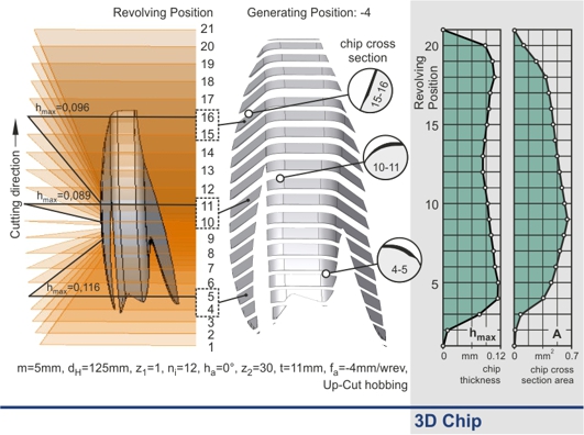
 Gear
hobbing is an efficient method of gear manufacturing. Due to the
fact that during the cutting process every hob tooth always cuts
in the same generating position, while in the various generating
positions the formed chip has different geometry, the resulting
tool wear is not uniform on any particular hob tooth. In order
to overcome this problem, the hob is shifted tangentially after
a certain number of cuts. Mathematical models to calculate the
progress of hob wear in the individual generating positions,
considering the existing process parameters, were presented. In
order to calculate flank wear regarding the complicated chip
geometry, equivalent chip dimensions, such as the cutting length
l, the chip thickness hs and the characteristic chip form (chip
group) were introduced. Based on these calculations, a computer
algorithm for the determination of the hob flank wear, which
depends on the shifting conditions, was presented.
Gear
hobbing is an efficient method of gear manufacturing. Due to the
fact that during the cutting process every hob tooth always cuts
in the same generating position, while in the various generating
positions the formed chip has different geometry, the resulting
tool wear is not uniform on any particular hob tooth. In order
to overcome this problem, the hob is shifted tangentially after
a certain number of cuts. Mathematical models to calculate the
progress of hob wear in the individual generating positions,
considering the existing process parameters, were presented. In
order to calculate flank wear regarding the complicated chip
geometry, equivalent chip dimensions, such as the cutting length
l, the chip thickness hs and the characteristic chip form (chip
group) were introduced. Based on these calculations, a computer
algorithm for the determination of the hob flank wear, which
depends on the shifting conditions, was presented.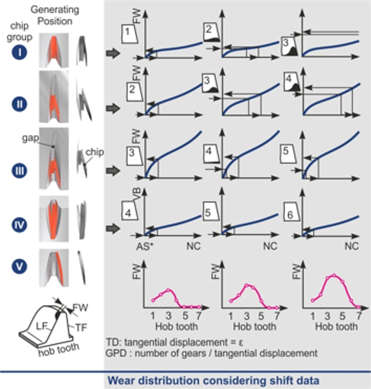 Simulating
the hobbing process with the aid of a computer program, it is
possible to determine the length, thickness and group of every
chip in the various cutting and generating positions. With the
aid of these parameters, the progress of the flank wear on a hob
tooth during cutting in the same generating position in all
successive cutting positions along the gear width can be
determined. This procedure is repeated for all generating
positions.
Simulating
the hobbing process with the aid of a computer program, it is
possible to determine the length, thickness and group of every
chip in the various cutting and generating positions. With the
aid of these parameters, the progress of the flank wear on a hob
tooth during cutting in the same generating position in all
successive cutting positions along the gear width can be
determined. This procedure is repeated for all generating
positions.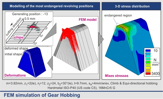 The
wide, almost exclusive, application
of gear hobbing, as a flexible
manufacturing process for external
gears has led to the thorough
description of its kinematics,
dynamics and tool wear mechanisms.
However, in various cases,
especially when cemented carbide or
coated tools are utilized, the
cutting tools experience critical
stress components, which are able to
cause premature tool failures. The
complicated kinematics, as well as
the particular tool geometry exclude
analytical stress filed solutions,
and require arithmetical ones
conducted with the aid of the finite
elements method. The computational
results explain sufficiently the
failure mechanisms, being in
agreement with corresponding
experimental data. The verified
parametric FEM model was further
applied for various cutting cases,
indicating the most risky cutting
teeth with respect to their failure
danger. Herewith, the optimization
of the cutting process is enabled,
taking into account that a proper
selection of cutting parameters can
eliminate the failure danger of
cutting tools, and achieve
satisfactory cost effectiveness.
The
wide, almost exclusive, application
of gear hobbing, as a flexible
manufacturing process for external
gears has led to the thorough
description of its kinematics,
dynamics and tool wear mechanisms.
However, in various cases,
especially when cemented carbide or
coated tools are utilized, the
cutting tools experience critical
stress components, which are able to
cause premature tool failures. The
complicated kinematics, as well as
the particular tool geometry exclude
analytical stress filed solutions,
and require arithmetical ones
conducted with the aid of the finite
elements method. The computational
results explain sufficiently the
failure mechanisms, being in
agreement with corresponding
experimental data. The verified
parametric FEM model was further
applied for various cutting cases,
indicating the most risky cutting
teeth with respect to their failure
danger. Herewith, the optimization
of the cutting process is enabled,
taking into account that a proper
selection of cutting parameters can
eliminate the failure danger of
cutting tools, and achieve
satisfactory cost effectiveness.