|
 The Power Skiving software simulates the gear manufacturing
process of Power Skiving. The software is implemented in a
commercial CAD environment which ensures increased accuracy of
the simulation. The main functionality includes the calculation
of a gear gap and the undeformed chip geometry as well as the
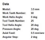
cutting forces produced during the process. A crucial parameter
of an accurate simulation is a correct cutting tool profile. In
power skiving the tool profile depends on the workpiece geometry
as well as on the tool inclination angle, known as shaft angle
Σ. Thus for each cutting case the tool profile is calculated in
the simulation software. The Power Skiving software simulates the gear manufacturing
process of Power Skiving. The software is implemented in a
commercial CAD environment which ensures increased accuracy of
the simulation. The main functionality includes the calculation
of a gear gap and the undeformed chip geometry as well as the
cutting forces produced during the process. A crucial parameter
of an accurate simulation is a correct cutting tool profile. In
power skiving the tool profile depends on the workpiece geometry
as well as on the tool inclination angle, known as shaft angle
Σ. Thus for each cutting case the tool profile is calculated in
the simulation software.
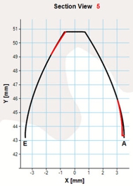
The calculated tool profile geometry is correctly positioned in
the 3D space according to the power skiving process kinematics
in order to produce the tool trajectory. During the profile
positioning. every movement involved in the process is
transferred to the cutting tool so as to decrease the complexity
of the simulation. The tool trajectory is used in order to
calculate the geometry of a gear gap by performing successive
cutting passes along the workpiece axis. During the gear gap
generation the undeformed chip geometry of each cutting pass is
calculated. It is important to mention that each generating tool
position used to calculate the gear gap, is contained in the
tool trajectory. Thus, each cutting tooth performs the exact
same 3D motion resulting in identical chip geometry between
different teeth for a same cutting depth. The undeformed chip
geometry can be later used in order to calculate the cutting
forces produced during the process.
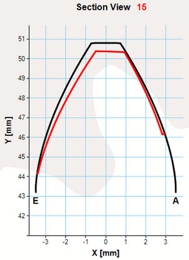
Τhe
chip geometry of each cutting pass is identical for every
cutting tooth, considering a stable depth of cut. However the
chip geometry greatly differs between internal and external
gears and it is modified depending on the axial feed of the
manufacturing process. In specific, for a same module and cross
axis angle, internal gear cutting chips are generally longer
than those of external gears. In addition, raising the axial
feed of the simulation chips with increased thickness are
produced and by increasing the Cross Axis angle of the cutting
tool, the chip is generally lengthened. The cutting forces are
calculated by sectioning the 3D chip geometry at each revolving
position of the tool trajectory. For each cutting section a 2D
geometry is produced, which gives valuable information about the
chip thickness and total area at the corresponding position. By
positioning the cutting section along with the tool geometry,
information about the affected tool area as well as the chip
thickness along the unrolled cutting edge is extracted.
According the Kienzle-Victor equations, given the process
material and cutting speed parameters the cutting forces at a
specific cutting section as well as the total forces may be
calculated. This is accomplished by separating the 2D geometry
into segments and calculating three force components for each
elementary segment, based on its area and height. The total
forces for each section constitute the total sum of the
transformed cutting force components of each segment in the
section coordinate system. The total forces of the manufacturing
process are produced by transforming the cutting forces of each
revolving position to the workpiece coordinate system. In this
step of the forces calculation, all teeth engaged in the process
should be taken into account, so that the total forces
calculation is correct.
Your contact:
Aggelos Marinakis
Tel.: +30 28210
37483
Mail:
amarinakis@isc.tuc.gr
|