|
 Twist
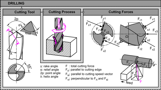
drills are geometrical complex tools
and thus various researchers have
adopted different mathematical and
experimental approaches for their
simulation. The present research
acknowledges the increasing use of
modern CAD systems and subsequently
using the API (Application
Programming Interface) of a typical
CAD system, drilling simulations are
carried out. Twist
drills are geometrical complex tools
and thus various researchers have
adopted different mathematical and
experimental approaches for their
simulation. The present research
acknowledges the increasing use of
modern CAD systems and subsequently
using the API (Application
Programming Interface) of a typical
CAD system, drilling simulations are
carried out.
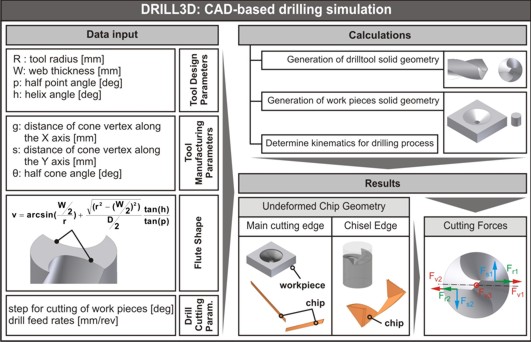
The developed
DRILL3D software routine, creates, via
specifying parameters, tool
geometries, so that using different
cutting conditions, realistic solid
models are produced incorporating
all the relevant data involved
(drilling tool, cut workpiece,
undeformed chip). The 3D solid
models of the undeformed chips
coming from both cutting areas (main
edges and chisel edge) are segmented
into smaller pieces, in order to
calculate every primitive thrust
force component involved with high
accuracy.
 The resultant thrust force
produced, is verified by adequate
amount of experiments using a number
of different tools, speeds and feed
rates. The final data derived,
consist of a platform for further
direct simulations regarding the
determination of tool wear, drilling
optimizations etc. The resultant thrust force
produced, is verified by adequate
amount of experiments using a number
of different tools, speeds and feed
rates. The final data derived,
consist of a platform for further
direct simulations regarding the
determination of tool wear, drilling
optimizations etc.
|
|
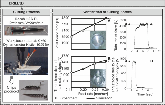 The
accuracy of the DRILL3D drilling
simulation model in calculating the
thrust force was verified executing
a series of experiments on a HAAS
3-axis CNC machine center with
continuous speed and feed control,
using a CK60 plate as the specimen.
A Kistler type 9257BA three
component dynamometer was positioned
between the machine center and the
work piece. The signal was processed
by a 5233A control type unit and
during the tests, the thrust force
was displayed graphically on the
computer monitor and analyzed so as
to enable early error detection and
ensure steady state condition. The
accuracy of the DRILL3D drilling
simulation model in calculating the
thrust force was verified executing
a series of experiments on a HAAS
3-axis CNC machine center with
continuous speed and feed control,
using a CK60 plate as the specimen.
A Kistler type 9257BA three
component dynamometer was positioned
between the machine center and the
work piece. The signal was processed
by a 5233A control type unit and
during the tests, the thrust force
was displayed graphically on the
computer monitor and analyzed so as
to enable early error detection and
ensure steady state condition.
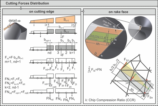 For
FEM analysis, the necessary force distribution along the cutting
edges, separately for each one of the edges involved, was
provided by the DRILL3D. Those forces were transferred to the FE
model following a two step approach: First, the forces from the
DRILL3D were directly distributed on the nodes of the cutting
edges. Second, the elementary forces FN applied on the nodes of
the cutting edges were further distributed on the appropriate
nodes that reside on the rake face of the tool and close to the
cutting edge. For
FEM analysis, the necessary force distribution along the cutting
edges, separately for each one of the edges involved, was
provided by the DRILL3D. Those forces were transferred to the FE
model following a two step approach: First, the forces from the
DRILL3D were directly distributed on the nodes of the cutting
edges. Second, the elementary forces FN applied on the nodes of
the cutting edges were further distributed on the appropriate
nodes that reside on the rake face of the tool and close to the
cutting edge.
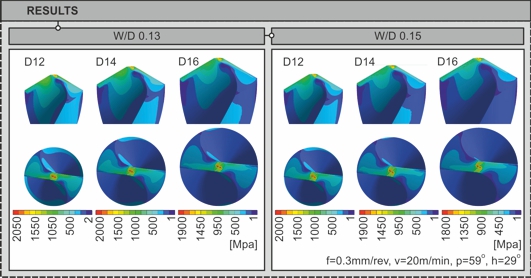 Next
figure depicts the maximum Von-Mises stress developed along the
chisel edge and the main edges for a number of tool diameters
(12mm, 14mm and 16mm) and web to diameter ratios (0.13 and
0.15), when the feed rate is 0.3mm/rev and the cutting velocity
is 20mm/min. As the tool diameter increases, for the same
cutting conditions, the level of the maximum stresses decreases.
Additionally, the increase of the web to diameter ratio results
in the decrease of the developed maximum stress for all cases.
In all simulations, the increase of the available contact area
when the drilling tool engages the workpiece, explains the
reductions in the Von-Mises maximum stress calculated. Next
figure depicts the maximum Von-Mises stress developed along the
chisel edge and the main edges for a number of tool diameters
(12mm, 14mm and 16mm) and web to diameter ratios (0.13 and
0.15), when the feed rate is 0.3mm/rev and the cutting velocity
is 20mm/min. As the tool diameter increases, for the same
cutting conditions, the level of the maximum stresses decreases.
Additionally, the increase of the web to diameter ratio results
in the decrease of the developed maximum stress for all cases.
In all simulations, the increase of the available contact area
when the drilling tool engages the workpiece, explains the
reductions in the Von-Mises maximum stress calculated. |